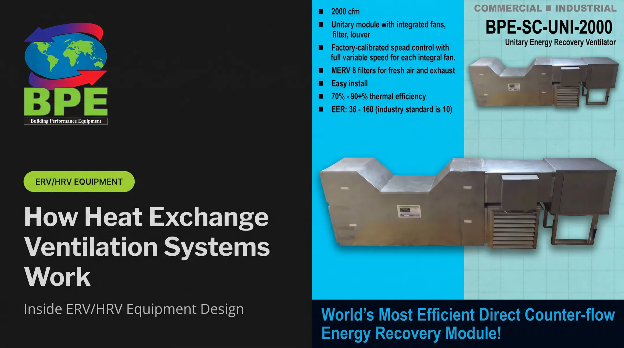

But the direction those streams travel matters more than most people realize. In a counterflow arrangement, hot and cold streams move in opposite directions through the exchanger. This keeps a meaningful temperature difference alive across more of the unit's length, compared to designs where streams travel the same way.
This article breaks down how counterflow heat exchangers actually work, how they stack up against parallel and crossflow designs, and what determines real-world performance once a unit is installed and running.
Key Takeaways
- Counterflow heat exchangers route hot and cold streams in opposite directions through separate channels.
- Opposing flow paths sustain the driving temperature difference and often beat parallel-flow designs on outlet-temperature control.
- Counterflow is a flow pattern used in plate, shell-and-tube, spiral, and air-to-air exchangers.
- Performance hinges on flow rates, inlet temperatures, surface area, fouling, pressure drop, and fluid properties.
What Is a Counterflow Heat Exchanger?
A counterflow heat exchanger is a device where two fluids or air streams travel in opposite directions while a conductive wall, plate, tube, or membrane keeps them physically separated. One stream enters where the other exits.
That separation matters. Heat passes through the dividing surface, but the fluids themselves remain separated.
This solves a specific operating problem: transferring usable heat between a process stream or ventilation airflow without contaminating one with the other, and without spending extra energy to heat or cool air that's already been conditioned.
Sensible heat vs. moisture transfer: Most flat-plate exchangers only transfer sensible heat, meaning temperature change alone. Designs with water-vapor-permeable plate material can also transfer moisture. That qualifies them for enthalpy (total-energy) recovery rather than sensible-only recovery, according to ASHRAE's Handbook chapter on air-to-air energy recovery equipment.
Why the Sustained Temperature Gradient Matters
Engineers describe the driving force behind heat transfer using the logarithmic mean temperature difference, or LMTD. It's a way of averaging the changing temperature gap along the length of an exchanger, rather than relying on a single inlet-to-inlet comparison.
For counterflow designs, the math pairs hot inlet against cold outlet, and hot outlet against cold inlet. ASHRAE's Handbook on heat exchangers uses this value, along with the overall heat-transfer coefficient (U) and transfer area (A), to calculate heat-transfer rate for a given design.
Because the temperature gap stays more consistent across a counterflow unit, the resulting LMTD is higher than in a parallel-flow arrangement with the same inlet conditions.
Construction Varies, the Principle Doesn't
"Counterflow" is a flow direction, not a product category. You'll find it applied across:
- Plate-and-frame exchangers
- Shell-and-tube units
- Double-pipe (tube-in-tube) designs
- Spiral exchangers
- Air-to-air energy recovery ventilators
Each format changes the geometry, materials, and fluid compatibility, but the underlying logic of opposing flows stays the same.
Building Performance Equipment's ERV line, for instance, specifies polypropylene or polyethylene flat-plate cores for general-purpose and corrosive-environment applications, built to meet ASTM D-1784 and D-2467/D-2665 standards where applicable.
How Does a Counterflow Heat Exchanger Work?
Hot and cold streams enter from opposite ends, exchange energy across a separating surface as they travel through, and exit with altered temperatures while never crossing paths. Here's how that plays out in practice.
Initiation
Flow starts when fans, pumps, dampers, or control valves push each stream into its own channel at opposite ends of the unit. Building Performance Equipment (BPE) installation guidance for comfort-to-comfort and process-to-comfort applications places supply and exhaust fans on the same physical side of the heat exchanger, while the airflows themselves travel in opposite directions through the core.
Operation can run continuously or respond to triggers like:
- Temperature setpoints
- Occupancy sensors
- Process demand
- Ventilation code requirements
Getting this stage right depends on a few non-negotiables: correct inlet and outlet connections, materials compatible with the fluids involved, adequate flow rates, and protection against freezing, overheating, or excess pressure.
BPE's duct-connection specs, for example, call for air velocities under 500 feet per minute except right at fan and heat-exchanger connections, with sheet-metal screws spaced every 6 inches and all seams sealed.
Core Operation
Once flow is established, heat moves from the warmer stream, through convection into the separating surface, through conduction across that wall or plate, and back out through convection into the cooler stream. It's a three-step handoff repeated continuously as long as both streams are moving.

The temperature profile along a counterflow exchanger is what sets it apart. The hottest section of one stream meets the warmest section of the opposing stream (not the coldest), while the cooler end of each stream continues exchanging heat near the opposite terminus. This pairing is what keeps the driving temperature difference from collapsing partway through the unit.
A side-by-side comparison of flow arrangements:
| Arrangement | Hot Stream Direction | Cold Stream Direction | Temperature Gap Along Length |
|---|---|---|---|
| Parallel flow | Enters left | Enters left (same end) | Large at the inlet, narrows sharply by the outlet |
| Counterflow | Enters left, exits right | Enters right, exits left | Stays more even across the full length |
| Crossflow | Enters left | Enters perpendicular (top) | Varies across both length and width |
ASHRAE's Handbook notes something counterintuitive that only happens in true counterflow setups: a temperature cross, where the fluid being cooled can actually exit at a lower temperature than the fluid being heated. That outcome isn't possible in parallel flow, no matter how the exchanger is sized.
BPE's own airflow documentation reports counterflow operation reaching up to 99% effectiveness in its tested configurations, compared with a ceiling closer to 75% for crossflow and 50% for parallel flow. Those are manufacturer-reported figures tied to specific units, not universal constants, but they illustrate the gap between arrangements.

Regulation and Control
Running a counterflow exchanger well means watching more than just inlet and outlet temperatures. Sensors typically track:
- Flow rates on both sides
- Pressure across the core
- Frost risk at low outdoor temperatures
- Bypass conditions for free cooling
- Abnormal pressure spikes signaling fouling or blockage
There's a constant trade-off between transfer performance and pressure drop. Narrower passages and greater surface area improve heat transfer, but they also demand more fan or pump energy to push fluid through.
ASHRAE's guidance on air-to-air recovery equipment ties pressure drop directly to friction and passage geometry, so every design choice that raises effectiveness carries an energy cost somewhere else in the system.
Practical safeguards include flow balancing, bypass dampers, filtration ahead of the core, cleaning access points, and alarms tied to fouling or pressure anomalies.
In cold climates, frost control becomes its own engineering problem. ASHRAE describes preheating incoming air and using face-and-bypass dampers to reduce core flow as outdoor temperatures drop. Some systems use exhaust-only defrost, letting warm exhaust air thaw the core while supply ventilation pauses temporarily.
BPE's heat-exchanger specifications note that units below -10°F and/or 40% relative humidity typically require application-specific assistance, reflecting how frost risk shifts the standard operating assumptions.
Output and Result
The end result of counterflow operation is straightforward: a warmer cold stream and a cooler hot stream. How much warmer or cooler depends on inlet conditions, flow capacity, available heat-transfer area, and how much heat gets lost along the way.
Engineers typically evaluate results against a few benchmarks:
- Heat-transfer duty – the actual rate of energy moved between streams
- Effectiveness – actual transfer compared to the theoretical maximum
- Outlet-temperature approach – how close the exiting stream gets to the entering temperature of the other side
- Pressure drop – the energy cost of pushing fluid through the core
- Fan or pump energy consumption – the operating cost tied to maintaining flow
ASHRAE's Handbook notes that counterflow air-to-air exchangers can theoretically approach 100% effectiveness, though typical field units land closer to 80%. That gap between theoretical and actual performance isn't a flaw in the concept. It's a reminder that leaks, fouling, uneven flow distribution, bypass air, and insulation losses all chip away at what a spec sheet promises.
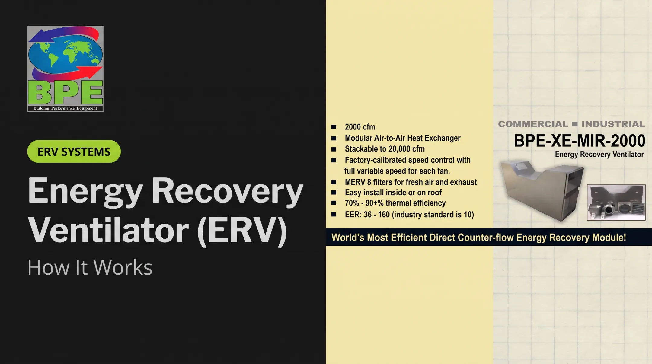
BPE's data on its XE-MIR-2000 model shows this range in action: sensible thermal efficiency reaches 96% at 500 SCFM but drops to 63% once flow climbs to 2,250 SCFM. Higher flow rates mean less contact time per unit of air, which lowers effectiveness even though the exchanger hasn't changed.
Where Are Counterflow Heat Exchangers Used?
Counterflow arrangements show up anywhere a facility needs to recover heat from one stream to precondition another, without mixing the two.
HVAC and Building Ventilation
In energy-recovery ventilation, outgoing exhaust air preconditions incoming outdoor air before it reaches a building's heating or cooling equipment. This can be sensible-only (temperature exchange) or total-energy/enthalpy recovery, which also transfers moisture.
A real-world example: two BPE-XE-MIR-2000 heat exchangers installed at the Red Bank YMCA supply 10,000 CFM of fresh outdoor air. Exhaust energy warms incoming air from a 20°F to 35°F range up to roughly 75°F, which cuts the mechanical heating load.

Industrial and Process Applications
Outside buildings, counterflow designs are common in:
- Waste-heat recovery from industrial exhaust streams
- Chemical processing and pharmaceutical production, where fluid separation is a safety requirement
- Food and beverage manufacturing, often with corrosion-resistant materials
- Refrigeration, where Alfa Laval's brazed-plate AC line is generally designed for countercurrent media flow
- Data-center cooling, where continuous, efficient airflow protects sensitive equipment
- Power generation, including closed-cycle systems that rely on opposing-flow heat exchangers in their thermal loop
A 2008 refinery case in Petroleum Technology Quarterly describes spiral exchangers using countercurrent flow to replace older units in FCC slurry-oil cooling. The same project installed eight spiral units in a visbreaking preheat train to recover process heat that would otherwise go to waste.
When Counterflow Makes Sense
Counterflow tends to be the preferred choice when a project needs:
- Tight control over outlet temperatures
- High thermal effectiveness in a compact footprint
- Consistent heat recovery from a continuous exhaust or process stream
Check these factors before you specify a unit:
- Operating temperature range and expected swings
- Flow rates on both sides
- Fluid or air cleanliness and corrosiveness
- Fouling potential and cleaning access
- Allowable pressure drop
- Leakage risk, especially where contamination matters
- Applicable code requirements
- Whether the application needs sensible-only or total-energy recovery
AHRI's 1060/1061 performance-rating standards give engineers a way to compare certified sensible and latent effectiveness, pressure drops, and exhaust-air transfer ratios across different manufacturers' units, rather than relying on marketing claims alone.
Building Performance Equipment builds air-to-air energy recovery equipment across that span, from 60-200 CFM residential modules to 2,000-20,000 CFM commercial and industrial systems. Before you assume counterflow performance, confirm the model's flow arrangement and published AHRI 1060 data—construction details still vary by model and application.
Conclusion
Counterflow heat exchangers work on one core principle: send two separated streams in opposite directions. Heat transfers across a temperature difference that holds up across more of the exchanger's length. That sustained gradient separates counterflow from parallel or crossflow designs under the same inlet conditions.
Choosing the right equipment means weighing several factors together:
- Flow arrangement and construction type
- Operating conditions and pressure drop
- Maintenance access
- Sensible-only versus total-energy recovery
None of those factors work in isolation. Get the combination right, and the equipment delivers the efficiency numbers on its spec sheet, not just the theoretical maximum.
Frequently Asked Questions
What is a counterflow heat exchanger?
A counterflow heat exchanger moves two fluids or air streams in opposite directions through separate channels. Heat transfers across a separating surface without mixing. The term describes the flow pattern, not a single product type.
Why is a counterflow heat exchanger more efficient than a parallel-flow heat exchanger?
Opposite flow directions keep a stronger average temperature difference across the exchanger's full length, instead of losing most of that difference near the inlet. Actual efficiency still depends on specific design details and operating conditions, not the flow arrangement alone.
What is the difference between a counterflow heat exchanger and a crossflow heat exchanger?
Counterflow routes streams in opposite directions along the same axis; crossflow routes them perpendicular to each other. Crossflow units often trade some thermal performance for a more compact footprint and lower pressure drop, depending on the application.
What are the main types of heat exchangers?
Common constructions include plate, shell-and-tube, double-pipe, spiral, finned, and air-to-air exchangers. Each of these can be built with counterflow, parallel-flow, or crossflow arrangements, so construction type and flow direction are separate decisions.
Can you show a diagram of parallel flow and counterflow heat exchangers?
In parallel flow, both streams enter from the same end and travel the same direction. In counterflow, streams enter from opposite ends and move in opposing directions. The comparison table earlier in this article shows both layouts.
How do you calculate the heat-transfer coefficient (HTC) for a heat exchanger?
HTC depends on fluid properties, velocity, flow regime, geometry, and surface condition. Calculate it from the Nusselt number (Nu = hL/k) using a convection correlation matched to your flow geometry; each design needs its own calculation.